Why REF required?????
REF protection applied on transformer in order to detect ground faults on a given winding more sensitively than overall differential protection able to do.
On which principle they based ?????
The principle of comparison of measured variables by comparing the residual current of the phase CT of the given winding with the current associated with ground star point.
Why residual current occur????? or why CT saturated???
Saturation Saturation is the sudden variation of material permeability from high value to low value at the point known as the saturation bend.
In case of saturation induction then increases only slowly and Ie ( excitation current ) deforms to form peak.
Why stabilizing resistor inserted in the differential path for REF relay ???
If any CT ( phase CT or neutral CT ) get saturation (due to DC component of current during trafo energization (Inrush current)) .
So CT 's high magnetizing inductance breaks down to low value determined by permeability of air.
Differential current or residual current caused by CT saturation does not flow completely through differential path (due to high Impedance in path) but flows through low magnetizing inductance of saturated CT.
Hence insertion of resistance has a restraining effect.
Voltage across stabilizing resistance at Max. through fault = Max. through fault current ( CT resistance + 2 * Cable resistance )
BTW we are never allow to saturate our CT's by selecting proper knee point voltage.
Monday, September 21, 2009
High and Low Impedance Relays
Both low impedance & high impedance are working in merz.-prize circulating current principle (i.e) under normal operating condition, incoming and out going current remains the same and hence no current flows through the relay operating coil.
Basic difference lies in how we are achieving the stability for external faults.
In low impedance relays, we have bias characteristics.Based on the external fault magnitude, bias increases.(in our
static relays, bias current is the average of incoming and outgoing currents) Operating current of the relay should exceed the setting current and the bias current.During internal fault condition all the current converges and hence operating current increases more than the bias and the relay operates.
In high impedance relays, stability is achieved by the external resistors connected in series with the relay operating coils and making it as voltage dependent.(this is why we call it as high impedance relays).Resistance should be calculated in such a way that the relay will not operate for the external fault (with one CT becoming completely saturated).
Monday, September 14, 2009
Electrical Interview Questions
- Tell us about your background.
- Your short term goals
- Your long term goals
- How can we trust if you stay with our organisation.
- GIS: Was there separate LCC and relay panels.
- What projects you have worked before?
- Why you want to work for us?
- What did you do in your particular job profile.
- How were you placed in that job profile
- Were you assisting or were you leading the team?
- Which group you would like to join - Relay, Automation, Electromechanical or Civil. and Why?
Electrical Interview Questions for Relay Protection Engineering III
- Have you also worked on Motor or generator protection or it is only transmission and distribution?
- What different kind of relaying you have worked with?
- Did you also work with Electromechanical relays?
- 78% of relaying is still electromechanical.
- Can you explain how do you order the relay from the Step 1 to commissioning?
- What type of relay you have used for SEL?
- What kind of protection is there for Line?
- Ok, it is distance.
- what is the distance protection philosophy?
- How many zones are there?
- Can you discuss the characteristic of the zone?
- How can you plot it on the paper?
- Where will be the protected line on the characteristic?
- What angle you can see the protected line?
- Can you discuss where will be the Remote line in this cureve?
- Where can you see the other lines on the R-X characteristic?
- Are you aware of line differential?
- What is the principle for the line differential?
- How does the differential takes place?
- Are you aware of POTT or DUB?
- Have you used them in your project?
- Which software you have used for ABB, simens for relay setting.
- What is REF?
- Why is it necessary?
- Why the differential relay cannot protect it?
- What is the philosophy of REF?
- Does it depend on the grounding?
- Are you aware of symmetrical components?
- Why are they used?
- What is the purpose of using symmetrical components?
- How you can measure fault using hte symmetrical components?
- What is unbalanced and balanced fault?
- Is 3Ph a balanced fault?
- Then what can be the unbalanced fault?
- How do you read the Voltage and current?
- How can you say that they are balanced?
- How can you make a graph of it?
- How is a displaced wrt b and wrt c?
- At what angle?
- what shall be the order of the abc?
- Can you give the example where you do phase chagne?
- What about the motor?
- How do you revrerse the direction?
- What did you study in your undergrad?
- What all things you learnt as a course work there?
- What are your goals 5-10 years down the line?
- can you explain the gap in your service?
- Have you worked on Aspen, Mathcad, before?
- We only work with SEl relays.
- What all books you have read for the relays?
- How did you learn the relay setting?
- How did you cross check the relay setting.
- Do you do hand calculation for hte relay setting?
- How was you site experience?
- Did you assist somebody or helped somebody for relay commissioning.
- How exactly you have worked on site?
- I am kind of surprised, how can you commission so many relays in 5 years.
- What kind of projects do you have?
- Have you read the papers from SEL ?
- How good are you with making presentations?
- Have you made presentation before?
- How good are you writing technical papers?
- How did you learn all this?
- What motivates you to work for us?
- What kind of load shedding knowledge do you have?
- How much familiar are you with Mark VI and load shedding at generation end?
- What application you have seen?
- Mainly you can focus on doing relay setting from the HMI?
- Can you explain your recent relay setting, how did you do it exactly?
- Did you make all calculations by yourself?
- Somebody else did for you?
Saturday, September 5, 2009
Load Flow Models are based on Static Network Model.
Utilities use real-time on-line models in SCADA for the optimization of generation, VAR control, losses, and tie-line control.
A load-flow study is carried out to determine the steady-state bus voltages, active
and reactive power flows, transformer tap settings, component or circuit loading,
generator exciter regulator voltage set points, system performance under contingency or emergency operations, and system losses.
Load flow can also be used to determine voltage profile at the time of starting a large motor. The starting motor is modeled as a constant-impedance shunt with the X/R ratio based on a locked rotor or starting power factor. The load-flow case is run with the starting motor disconnected, and the voltage at the relevant buses is recorded. The starting-motor locked-rotor impedance
is connected as a shunt, and the new case is run. The difference in voltage at any bus
is the voltage drop at the instant of starting the motor.
Two algorithms, Gauss-Siedel and Newton-Raphson, are used to solve the loadflow
equations.
The Gauss-Siedel method gives a simple and stable solution and works well up to 100 buses. The
solution iterates one bus at a time, corrects that bus voltage to the specified value, and continues until an error is detected.
The solution may not converge for the following reasons:
1. Error in the input data
2. System is too weak to carry the load
3. Insufficient VAR in the system to support the voltage
In the Newton-Raphson method, the n quadratic equations are first linearized by forming a Jacobian matrix. The present value of the bus voltage is then calculated, and then n linear equations are solved in steps. The number of iterations is small, between five and ten.
Friday, September 4, 2009
Electrical Interview Questions for Relay Protection Engineering
- There will be always a lot of questions based on your resume. You should know your resume and what all things you have done in your project in a nice manner.
- There will be also a lot of cross questioning about the profile you are looking for.
- But apart from that, few basic questions might be asked to you:
- What factors decide the pick up value of the current, considering distributed system.
- What are the time margin for the overcurrent relay.
- How are CT's connected on Delta-Star trafo considering you are not using any phase correcting CTs or any interposing CTs.
- What are the inputs needed for Breaker Failure relay.
- What is Zone 1 setting?
- Why it is set to that percentage?
- Say, PTR = 1000/1 and CTR = 200/1; what shall be Secondary Impedance.
- What sequence current flows through P-G faults?
- How does they flow?
Monday, August 31, 2009
IInd Technical Interview with Power Company, US
- I have your resume with me, is that correct you have worked in Siemens, ABB and Areva Relays before?
- What kind of work you have done with relays?
- Which project you have worked on?
- Have you done commissioning of relays yourself or just witnessed the relay commissioning?
- Have you done relay setting calculations yourself?
- Have you worked with GE and SEL relays before?
- Yes, I understand that if you have worked on prior relay knowledge, you can learn other relays too.
- You also have Control experience?
- what type of control experience do you have?
- I mean, Automation Contorl.
- Have you also worked on Schematics before?
- What type of schematics you have worked before - Single Line, 3 line, can you tell me all of them?
- How soon can you join us?
- How about your studies? When will you completing it?
- Are you ready to relocate?
Sunday, August 30, 2009
Series and Shunt Reactors in Power system
Shunt Reactor are used for reactive compensation:
During normal operation of an electrical power system, the transmission and distribution voltages must be maintained within a small range, typically, from 0.95 to 1.05 pu of rated value. Due to the load variations, shunt reactors and capacitors have been applied in
power systems to compensate excess reactive power (inductive for heavy load conditions, and capacitive for light load conditions). Shunt reactors are commonly
used to compensate the capacitive reactive power of transmission and distribution systems and thereby to keep the operating voltages within admissible levels.
Series Reactor for limiting the fault current.
Reference:
http://www.ritzusa.com/pdf/TECH%20NEWS_SHUNT_71665.PDF
Saturday, August 29, 2009
PC Based SCADA software
ABB PC based automation system: MicroSCADA
Software tool used: Substation Monitoring System (SMS)
----------------------------------------------------------------
Siemens PC based automation system: SIMATIC PAS
----------------------------------------------------------------
Areva PC based automation system: PACiS
Software tool used: Substation Monitoring System (SMS)
----------------------------------------------------------------
Siemens PC based automation system: SIMATIC PAS
----------------------------------------------------------------
Areva PC based automation system: PACiS
Relay Protection Setting Software
ABB relay setting software: CAP540
Siemens relay setting software: DIGSI 4.0
Areva/Micom relay setting software: S1
Siemens relay setting software: DIGSI 4.0
Areva/Micom relay setting software: S1
Wednesday, August 26, 2009
Electrical Automation Interviews
- Tell us about your background.
- What SCADA systems are you aware of?
- Have you worked on ODC server before?
- Describe your experience in Automation Control?
- Have you worked on Embedded System before?
- Describe your experience on that?
- Tell us how you did Relay coordination?
- Say for e.g. there are two feeders, one incoming and other outgoing, how do you achieve relay coordination on them.
- Have you done Short Circuit studies?
- What tools have you used before?
- Tell us how will you calculate busbar earthing? What values of Earthing / Leakage current is fine for Bus bar earthing in panel.
- How is HMI prepared?
- What ethernet switch did you use for connecting IEDs?
- Which make of ethernet switch did you use?
- How was the architecture / communication topology.
Interview for Relay Protection Engineer
- How are you today?
- How do you think that you are suitable for the job?
- So, you are saying that you have experience with Siemens Relays, Relaying software, Communication topology and you have worked before on the projects, how confident are you to work for this work profile? Can you elaborate or explain in detail.
- How all these things will help you better perform the job?
- Can you tell me how many relays you have worked for? i.e. how many protection relays from Siemens, ABB, GE, SEL you have actually used in the projects?
- Can you tell me if you have commissioned all of them by yourself?
- Can you quantify the numbers you have used in the projects?
- How did you configure these relays?
- What software is used to configure ABB, Areva relays?
- Were there different engineers to configure ABB, Siemens relays?
- Have you worked on Automation ?
- How do you do relay settings?
- How does two relay communicate with each other?
- What protocols are you familiar?
- Have you worked on Profibus or IEC-103 before?
- What parameters does IEC-61850 transfer? Is it just protection only? Or non protection parameters are also transferred?
- Have you worked on HMI before?
- Have you used software to build HMI?
- How does trigger, alarm or trip or event logs are configured on HMI?
- How many IEDs connect to the Ethernet Switch?
- What is the limitation of connecting the IEDs to the switches?
- What other communication protocols are you familiar?
- How will the relay communicate with the other relay? Say, there are two relays , say trafo, one on HV side and other on LV side, how will they communicate with each other?
- Tell me how good are you with travelling?
- Can you travel all the time?
- If not, give me the % you can travel?
- What traits you are looking in for a manager you will be working with ?
- What personal traits you will not like your manager to have?
- Do you have any personal limitations, what you cannot do?
- How long can you work? I mean how long will be the working hours you can put up?
- How much comfortable are you with night travelling?
- Can you describe any challenges in the work before, which you can describe or give details?
- These are the technical challenges. What abou the personal challenges you have faced in work?
- What if you dont like any thing particular with your boss? how will you cope up with that?
- How soon can you join us?
- What are your aspirations?
- Why did you choose your masters in Computer Science?
- Can you elaborate on your work experience?
- Have you commissioned the relays before?
- How do you trouble shoot the relays?
- Has your experience only upto protection or you have with automation too?
- Are you familiar with preparing drawings in Autocad / Elcad /Microstation?
- How good are you with them?
- Do you know how to exactly draw drawings?
- What kind of drawings are you familiar with?
- One, Three line, SLD, Logic diagrams, relay, cut outs, which ones?
- For how long do you have experience in them?
- What causes trigger in the HMI?
- What causes alarm in the HMI?
Tuesday, August 18, 2009
Current Transformer Requirement
1. Typically the c.t. is specified by means of an accuracy factor and an overcurrent factor up to which the c.t. remains accurate with the maximum specified burden connected to its secondary, eg:
5P10 : 5VA (Accuracy Limit, Overcurrent Factor : Maximum Burden(at c.t. secondary level))
In the example of a 5P10, 5VA c.t., this will transform primary current within the accuracy limit of 5% when a burden of 5VA (at rated current) is connected to the c.t. secondary, for a primary current up to 10 times its rating.
2. Knee Point Voltage: The Knee point voltage of the current transformers should be at least twice the relay setting voltage. The knee point voltage is expressed as the voltage at fundamental frequency applied to the secondary circuit of the current transformer which when increased in magnitude by 10% causes the magnetising current to increase by 50%.
Pole discrepancy protection
This function ensures that any one or two poles of a circuit-breaker do not remain open for longer than an independently settable time (i.e. unsymmetrical conditions). This time stage is initiated when current (above the set value) is flowing in any 1 or 2 phases, but not in all 3 phases. Additionally, the circuit-breaker auxiliary contacts (if connected) are interrogated and must show the same condition as the current measurement. Should this time delay expire, then a three-pole trip command is issued. This function is normally used when single-pole auto-reclosing is applied.
Reference:
1. www.siemens.com/easy-line
Reference:
1. www.siemens.com/easy-line
Interview Questions on Relay and its fundamentals
- What is the objective of relaying system?
- What are the functional requirements of the relays?
- Can you draw the healthy trip circuit?
- What are switchgears?
- What are the different types of switchgear?
- What are the operating mechanisms of the switchgear?
- What are through faults?
- What is relay burden?
- Why stabilizing resistor are used?
- How do you calculate the value of the stabilizing resistor?
Anti pumping relay and its operational concept
The anti-pumping relay allows the breaker to close only once for each press of the 'close' pushbutton (or rotation of the handle) or Anti-pumping relay cancels the persistent closing
signal after successful completion of the closing operation.
If a fault exists on the circuit before the breaker is closed, the breaker will close and immediately trip before the operator has a chance to release the close button (or handle). The anti-pumping relay prevents the still-active close signal from trying to reclose the breaker.
Many breakers are not rated for multiple successive reclose operations. If an anti-pumping relay is not used, the rapid close-open-close-open... series can result in destruction of the breaker and harm to the operator.
Trip Cirucit Supervision Relay
The supervision relay type TCS is intended for a continuous supervision of circuit breaker trip
circuit and to give an alarm for loss of auxiliary supply, faults on the trip-coil or its wires independent of the breaker position, faults on the breaker auxiliary contacts and faults in the
supervision relay itself.
The following diagarm explains how the trip circuit supervision relay works:
 There are 3 scenarios:
1. Supervision in preclose condition.
2. Supervision in postclose condition.
3. Supervision with latched trip or protection relay.

Reference: http://www02.abb.com/global/inabb/inabb509.nsf/0/51663da1af2c5e9f652571bc00388c76/$file/TCS+Brochure.pdf
Electrical Interview Questions on Protection ( Busbar, Buscoupler, Bussection, Feeder, Trafo)
- Explain Busbar protection?
- Explain Bus Coupler protection?
- Explain Bus Section protection?
- Explain Feeder protection?
- Explain Line protection?
- Explain Transformer protection?
- Explain Motor Protection?
- Explain Shunt reactor protection?
- What is trip circuit supervision relay?
- What is post and pre condition for trip circuit supervision relay?
- What are lock out relays?
- What is isolator replica. How it is used?
- What is dead zone?
- How faults are detected in dead zone?
- Case 1: Consider one CT - - Case 2: Consider two CT
- - Case 3: Consider CTs not covering Breaker and CT zone.
- How many bay units can be configured to Central unit in Busbar protection?
- What is the need of duplicating lock out relays?
- How groups are formed for each protection to lock out relays?
- Why DC is duplicated?
- Why relays are duplicated to achieve similar protection?
- How is signal list prepared?
- How synchronization takes place?
- What is check zone?
- What is discrimination zone?
- Which type of cable used for connecting IEDs?
- Which type of cable used for PC to IED?
- Which type of connector used for FO cable to connect to IED?
- What information Bay unit have?
- What is self monitoring of relays?
- what are high impedance schemes?
- What are low impedance schemes?
- Where are 31. and 32. used?
- For differential protection, what tripping conditions must be fulfilled?
- Explain the Breaker failure logic?
- Explain intertrip?
- Explain, how or logic for intertrip during Busbar operation?
- What type of relay senses closing onto fault?
- How are disconnector monitored?
- How is breaker fail monitored from maloperating?
- How are settings of busbar protection achieved?
- What do you do to distance protection, when Voltage transformer's MCB (miniature circuit breaker trips)?
- What are the annunciation in Feeder protection?
- What is the switching order to close earth switch?
- What is the switching order to close circuit breaker?
- What is automatic switching?
- What is on load transfer?
- What is to be taken care of while closing disconnector?
- What is pole discrepancy relay?
- What is anti pumping?
- What can be problems with Circuit breaker?
- What are SF6 Stages for alarm and trip for circuit breaker?
- When does Circuit breaker lock out?
Monday, August 17, 2009
“Equipment intended to interrupt current at fault levels shall have an interrupting rating sufficient for the nominal circuit voltage and the current that is available at the line terminals of the equipment. Equipment intended to interrupt current at other than fault levels shall have an interrupting rating at nominal circuit voltage sufficient for the current that must be interrupted.”
- Q: Why is making capacity of circuit breaker higher than making capacity of Circuit breaker?
- Q: What are the values of making capacity of circuit breaker?
- Q: What are the values of breaking capacity of circuit breaker?
- Q: Define the terms ? Breaking capacity, making capacity.
- Q: Distribution equipment, such as circuit breakers, fuses, switchgear, and MCCs, have interrupting or withstand ratings defined as the maximum rms values of symmetrical current.
- Q: What is Circuit breakers breaking capacity ? Answer: A circuit breaker can't interrupt a circuit at the instant of inception of a short. Instead, due to the relay time delay and breaker contact parting time, it will interrupt the current after a period of five to eight cycles, by which time the DC component will have decayed to nearly zero and the fault will be virtually symmetrical.
- Q: What is Circuit breaker's making capacity? Answer:Closing a breaker against an existing fault makes it possible to intercept the peak of the asymmetrical short-circuit current, which is greater than the rms value of the symmetrical current. For this reason, equipment is also tested at a particular test X/R ratio value typical to a particular electrical apparatus, such as switchgear, switchboards, or circuit breakers, and is designed and rated to withstand and/or close and latch the peak asymmetrical current described above.
- Q: Why fault analysis is required? Answer: Fault analysis is required to calculate and compare symmetrical and asymmetrical current values in order to select a protective device to adequately protect a piece of electrical distribution equipment.
Reference:
- This site has 5 sections - Substation, High Voltage, Transformers, Protection, Commissioning. It is good for having an overview and going in detail in few areas. http://www.sayedsaad.com/Protection/index.htm
- This site has lot of material and books on electrical. http://www.blogger.com/2.%20http://www.filecrop.com/search.php?w=Practical%20Power%20System%20Protection&opt_t=1&opt_d=0&c=30&m=&size_i=&size_f=&engine_r=&engine_m=&pos=1&order=score&mod=dec
- http://ecmweb.com/training/electrical_basics/
Friday, August 14, 2009
Loading Sample Projects from Eclipse to Emulator
Assuming that Android SDK, Eclipse SDK and Android Development Tools are updated. 
- Open Eclipse.
- File->New->Android Project
-

- New Android Project window comes up. Select: Create project from existing source; Provide-> Location: (Browse to the current folder having sample examples. In case of Android 1.5, samples are located in Platforms\android-1.5\samples).
- Choose Build Target -> Android 1.5

- Right click on the project -> Snake -> Run as -> Android Application
-

- Check the log window below. It will show the status of the Snake, getting installed on the android emulator.
-

- The application gets loaded on the emulator and the screenshot is as follows:
-

- When you hit 'Up' tab,the game will run.
Rotating Emulator Screen as per the application need.
- Run android emulator.
- It comes up with vertical orientation.

- Now there are some applications which only run on horizontal layout. Like the one below:

- Press Control + F12 (function key F12). It will rotate the screen to horizontal layout.

- This is how it will work.

Installing API Demos/Samples on Android Emulator and features on APIDemo.
- If you are running android-1.5, then, you can run samples from both android 1.1 or android 1.5 or both. However to load API demos on emulator I used android 1.1 version.
- Hence go to - C:\android-sdk-windows-1.5_r3\platforms\android-1.1\samples
- The following samples codes are provided:
- ApiDemos, HelloActivity, Home, LunarLander, Notepad, SkeletonApp, Snake.
- To load ApiDemos, follow the instruction on Loading Sample Projects from Eclipse to Emulator .
- To Run the project go to Run Configurations and
- Choose Build Target - Android 1.1.
- And then continue exactly as mentioned in the above article.
- You can see that lot of applications are provided by APIDemos. Such as App, Content, Graphics, Media, OS, Text, Views.

- Following are the views provided: Animation, Auto Complete, Buttons, Chronometer, Controls, Custom, Date Widgets, Expandable Lists, Focus, Gallery, Grid, ImageButton, ImageSwitcher, ImageView, Layout Animation, Layouts, Lists, MapView, MapView and Compass, Progress Bar, Radio Group, Rating Bar, ScrollBars, Seek Bar, Spinner, Tabs, TextSwitcher, Visibility, WebView.

- Animations further can have 3D Transition, Push, Shake and they have further categorized. Please click the slide show to see all the views of Animations.

- Slideshow of all the Views.
- It also have media Player and you can run Media Player or VideoPlayer on it.

- Similarly Graphics has a lot of features. Features available on ApiDemo are: AlphaBitmap, AnimateDrawables, Arcs, BitmapDecode, BitmapMesh, CameraPreview, Clipping, ColorMatrix, Compass, CreateBitmap, Drawable, FingerPaint, Layers, MeasureText, OpenGL ES, PathEffects, PathFillTypes, Patterns, Pictures, Points, PolyToPoly, Regions, RoundRects, Scale to Fit, SensorTest, SurfaceViewOverlay, Sweep, TextAlign, Touch Paint, Typefaces, UnicodeChart, Vertices and Xfermodes.
- To view some of the features on Graphics, please click the slide show.
Monday, August 10, 2009
Most asked non technical questions
- Have you worked on *** before? (*** is not in your resume or probably you never worked on it before).
- What do you want to do?
- What is your favorite *** (programming language, tool or product) ?
- What is your work style ?
- Tell me about your experience.
- What are your career goals?
- Why are you looking to change jobs?
- How much money do you want to make?
- What is your salary history?
- Why should we hire you?
- Do you have any questions for me?
- Why are you suitable for this job?
- What are your relevant skills and experience?
- What makes you a good candidate?
- What are your strengths and weaknesses?
- Why are you interested in this vacancy?
- What are you looking for in your next job?
- Why are you looking?
Thursday, August 6, 2009
User Interface Links for Android
- User Interface (UI) designer/editor for programming the Android Cell Phone Platform. This has the tool for auto generating code for the basic Widgets. http://www.droiddraw.org/

- This site explains have good material for basic learning. http://www.droidnova.com/playing-with-graphics-in-android-part-i,147.html

Android Views
- SurfaceView
- View
- ViewStub
- AnalogClock
- AutoCompleteTextView
- Button
- CheckBox
- Chronometer
- DatePicker
- DigitalClock
- EditText
- Gallery
- ImageButton
- ImageView
- MultiAutoCompleteTextView
- ProgressBar
- RadioButton
- RatingBar
- SeekBar
- Spinner
- TextView
- TimePicker
- ToggleButton
- TwoLineListItem
- VideoView
- ZoomButton
- ZoomControls
- include
Wednesday, August 5, 2009
Android Layouts
- AbsoluteLayout
- DialerFilter
- ExpandableListView
- FrameLayout
- GridView
- HorizontalScrollView
- ImageSwitcher
- LinearLayout
- ListView
- MediaController
- RadioGroup
- RelativeLayout
- ScrollView
- SlidingDrawer
- TabHost
- TabWidget
- TableLayout
- TableRow
- TextSwitcher
- ViewAnimator
- ViewFlipper
- ViewSwitcher
- merge
Android Widgets
| Graphical display | Code |
| AbsoluteLayout |
|
|
Analog Clock | |
|
Button |
|
|
CheckBox | |
| Chronometer |
|
| DatePicker | |
|
DigitalClock | |
|
EditText | |
| FrameLayout |
|
| Gallery | |
| ImageButton | |
| ImageView | |
| LinearLayout |
|
|
ProgressBar | |
|
RadioButton | |
| RelativeLayout |
|
|
Spinner | |
|
TextView | |
| TimePicker | |


----------------------------------------------------------------------------------------------------------------------
Reference:
1. A Visual Guide to Android GUI widgets http://www.droiddraw.org/widgetguide.html
2. Android Developers on widgets supported by android 1.5 SDK.
http://groups.google.com/group/android-developers/msg/a5247467151f5e3a
Tuesday, August 4, 2009
Interview Questions on Transformer Protection
- Q. What parameters or technical particulars are important to be considered while designing protection scheme of the transformer? Answer:
- Network Diagram showing the position of the transformer in the system
- kVA or MVA rating of the transformer
- Fault Level at the transformer
- Voltage Ratio
- Winding Connections
- Per Unit Impedance
- Neutral Point Earthing Resistance
- Value of the System Earthing Resistance
- Whether Indoor or Outdoor
- Dry or Oil Filled
- Length and area of cross section of the connecting leads between CTs and Relay Panel
- Q. What can be the reasons for the failure of the transformer? Answer: Transformer is one of the most expensive equipments in the Power System. Failure of the transformer can cause outage of power supply for even days. However, multiple things can go wrong with the transformer: There can be two types of failure - Internal Faults and External Faults.
- Internal Faults (the faults within the transformer):
- Core Failure
- Winding Failure
- Lamination Failure
- Bushing Failure
- Terminal Board Failure
- Tap Changer Failure (OLTC failures)
- Transformer Oil
- Oil level low
- Moisture absorption
- Transformer cooling system
- Failure of insulation between Lamination and Core Bolt
- Badly made joints and connections.
- Frequent exposure to Lightning strokes
- External Faults (the faults outside the transformer):
- OverLoad ... increases copper losses and consequence temperature rise.
- Through Faults or System Faults ... not detected by differential protection of transformer, however, if through faults persist for longer duration, transformer gets damaged by thermal and electromagnetic mechanical stress ... detected by overcurrent relays.
- Short Circuits
- Open Circuits
- Earth Faults
- Over Voltage
- Reduced system frequency
- Q. How Transformer Protection provided for internal faults? Answer:
- Bucholz Relay (1st Stage Alarm and 2nd Stage Trip)
- Sudden Pressure Relay (1st Stage Alarm and 2nd Stage Trip)
- Pressure Relief Valve (1st Stage Alarm and 2nd Stage Trip)
- Pressure Switch (1st Stage Alarm and 2nd Stage Trip)
- Oil level Gauge Indicator (Alarm)
- Vacuum Level Indicator (Alarm)
- Oil Temperature Indicator (Alarm)
- Gas Temperature Indicator (Alarm)
- Silicon Breather (Passive - no alarm)
- Smoke Detector (Alarm)
- Q. How Transformer Protection provided for external faults? Answer:
- Differential Protection
- Restriced EarthFault Protection
- Over Current Protection
- Over Fluxing Protection
- Over current relays with under voltage blocking
- Zero sequence protection.
- Negative phase sequence protection
- Q. What are the tests done to minimize internal faults? Answer:
- Dissolved Gas Analysis (DGA): Faults due to arcing, high current breakdown of oil, localized sparking, partial discharge of oil, localized overheating or hot spots, etc. causes thermal degradation of oil and used for analysis.
- Thermography of Transformer: Hot Spots on the transformer bushing, circulation of oil in radiator tubes, distribution of heat on transformer body, etc.
- Capacitance Tan Delta: to detect oil degradation.
- Oil Sample Test: to check the oil quality.
- Q. What are the reasons for Oil degradation? Answer:
- Degradation
- Oxidation
- Contamination
a) Dielectric breakdown voltage indicates the presence of electrically conductive contaminants in oil.
b) Interfacial tension and acid number (sometimes called neutralization number or acidity) are affected by oxidation and contamination.
c) Water content is temperature dependent.
d) Power factor is also temperature dependent.
- Q. What protection are provided to transformer depending on their kVA or MVA ratings?
-
Protection
Transformer Rated below 500 kVA
Transformer Rated between 500 kVA - 5MVA
Transformer Rated above 500 kVA
Differential
No
No
Yes
Restricted Earth Fault
No
No
Yes
Back Up Over Current
No
Yes
Yes
Back Up Earth Fault
No
Yes
Yes
Over Fluxing
No
No
Yes
Fuses
Yes
No
No
Bucholz, PRV, OSR
No
Yes
Yes
Oil and Winding Temperature Indicator
No
Yes
Yes
Oil level monitoring equipment
No
Yes
Yes
- References:
- Basler: Transformer Protection Application Guide http://www.basler.com/html/html/transformer.htm
- IEEE Guide for Protective Relay Applications to Power Transformers (IEEE Std C37.91-2000)
- Dissolved Gas Analysis Wiki http://en.wikipedia.org/wiki/Dissolved_gas_analysis
- Thermography of transformer. http://us.fluke.com/usen/Solutions/TI/Thermal-Imaging-Electrical-Systems.htm
- Implementation of Thermography in Power utilities www.ndt.net/article/afndt2008/papers/tahir.pdf (good material on what is thermography and its basic concept).
- Capacitance Tan Delta test http://cr4.globalspec.com/thread/32684#comment341158
Monday, August 3, 2009
More commands on -AVD to create, delete, move, update...
Usage:
=====================================================
android [global options] action [action options]
=====================================================
Global options:
-h --help This help.
-s --silent Silent mode: only errors are printed out.
-v --verbose Verbose mode: errors, warnings and informational messages are printed. =====================================================
Valid actions are composed of a verb and an optional direct object:
================================================
- list : Lists existing targets or virtual devices.
Action "list ":
Lists existing targets or virtual devices.
Options:
No options
=====================================================
- list avd : Lists existing Android Virtual Devices.
Action "list avd":
Lists existing Android Virtual Devices.
Options:
No options
=====================================================
- list target : Lists existing targets.
Action "list target":
Lists existing targets.
Options:
No options
=====================================================
- create avd : Creates a new Android Virtual Device.
Action "create avd":
Creates a new Android Virtual Device.
Options:
-t --target Target id of the new AVD [required]
-c --sdcard Path to a shared SD card image, or size of a new sdcard for the
new AVD
-p --path Location path of the directory where the new AVD will be created
-n --name Name of the new AVD [required]
-f --force Force creation (override an existing AVD)
-s --skin Skin of the new AVD ====================================================
- move avd : Moves or renames an Android Virtual Device.
Action "move avd":
Moves or renames an Android Virtual Device.
Options:
-p --path New location path of the directory where to move the AVD
-n --name Name of the AVD to move or rename [required]
-r --rename New name of the AVD to rename
====================================================
- delete avd : Deletes an Android Virtual Device.
Action "delete avd":
Deletes an Android Virtual Device.
Options:
-n --name Name of the AVD to delete [required]
for eg.
D:\android-sdk_1.5_windows_16july\tools>android delete avd -n avd51
AVD 'avd51' deleted.
====================================================
- update avd : Updates an Android Virtual Device to match the folders of a new SDK.
Action "update avd":
Updates an Android Virtual Device to match the folders of a new SDK.
Options:
-n --name Name of the AVD to update [required] ====================================================
- create project: Creates a new Android Project.
Action "create project":
Creates a new Android Project.
Options:
-k --package Package name [required]
-n --name Project name
-a --activity Activity name [required]
-t --target Target id of the new project [required]
-p --path Location path of new project [required]
=====================================================
- update adb : Updates adb to support the USB devices declared in the SDK add -ons.
Action "update adb":
Updates adb to support the USB devices declared in the SDK add-ons.
Options:
No options
=====================================================
Saturday, August 1, 2009
How to capture Screen of the Android Phone or emulator?
- Run emulator either using cmd or eclipse.
- If device i.e. Android Phone, connect it with the PC using specific cable use to load Apps.
- Go to Eclipse.
- Go to Devices as shown in A.

- Check for Circle B, it is Screen Capture,it will get the current instance of the emulator or Android Phone (device).

- Go to Save.
- It will save the screen as a .png file as shown below.

Friday, July 31, 2009
How to Install Games/Applications on Your Android Phone or Emulator
- This is how you can directly install any applications or Games and check the working of the Touch Screen on Android Phone.
- Make sure that Phone is powered up and on. If using Emulator, create the Emulator Instance and it is running.
- However, if emulator and Phone both are running, the command will run only on emulator. So, you have to quit the emulator instance, when loading the app on the Phone.
- This shows that the Phone is being detected by the PC.
- D:\android-sdk_1.5_windows\tools>adb devices
- List of devices attached
? device - This shows how to load the games on the actual phone or emulator.
- D:\android-sdk_1.5_windows\tools>adb install Puzzles.apk
1300 KB/s (1352247 bytes in 1.015s) - D:\android-sdk_1.5_windows\tools>adb install Snake.apk
244 KB/s (19545 bytes in 0.078s) - D:\android-sdk_1.5_windows\tools>adb install Android_Sudoku.apk
601 KB/s (741288 bytes in 1.203s) You can download few Game Apps from the below site for free.
http://www.androidfreeware.org/download

Thursday, July 30, 2009
How to Create Two or multiple instances of Emulator
- cmd1 ... D:\android-sdk_1.5_windows\tools>android create avd -n avd1 -t 1
Android 1.5 is a basic Android platform. Do you wish to create a custom hardware profile [no] Created AVD 'avd1' based on Android 1.5 - cmd1 ... D:\android-sdk_1.5_windows\tools>android create avd -n avd2 -t 1
Android 1.5 is a basic Android platform. Do you wish to create a custom hardware profile [no] Created AVD 'avd2' based on Android 1.5 - cmd1 ... D:\android-sdk_1.5_windows\tools>D:\android-sdk_1.5_windows\tools>emulator –avd adv1
- cmd2 ... D:\android-sdk_1.5_windows\tools>emulator –avd adv2
- Two emulator instances are created. One with Port 1 = 5554 and other with Port 2 = 5556.

- Similarly multiple instances of the emulator can be created by creating multiple AVDs and running emulator deploying those AVDs.
- AVD can be easily created using ECLIPSE too.
- Go to Eclipse -> Run Configurations -> Target tab

- You can see the list of all the existing AVDs.
- Now go to AVD Manager (Android Virtual Devices Manager) and choose the option of Create AVD as in the next window.

- You can also Delete AVD ... go back to AVD Manager and select the particular AVD.

- You can create emulator instance directly from the ECLIPSE.
- Eclipse -> Run Configurations -> Target -> Select a preferred AVD for deployment and then RUN.


How to Create SD Card?
The following commands will create, mount the SD card and finally push the songs to the SD card and emulator playing those songs/pictures.
- C:\android-sdk-windows-1.5_r3\tools>mksdcard -l sd500m 500M C:\android-sdk-windows-1.5_r3\tools\mysdcard.img ...... mksdcard: create a blank FAT32 image to be used with the Android emulator
usage: mksdcard [-l label]
ifis a simple integer, it specifies a size in bytes
ifis an integer followed by 'K', it specifies a size in KiB
ifis an integer followed by 'M', it specifies a size in MiBto create sdcard - The following size file will be created in tools directory of android-SDK. You can also create SD card with any memory size - say, 256M, 512M, 1024M, 2048M.

- To mount on emulator without specifying -avd C:\android-sdk-windows-1.5_r3\tools>emulator -sdcard mysdcard.img
emulator: ERROR: You did not provide the name of an Android Virtual Device
with the '-avd' option. Read -help-avd for more information.
If you *really* want to *NOT* run an AVD, consider using '-data'to specify a data partition image file (I hope you know what you're doing). However, this command will work fine with android-sdk-windows-1.0_r1 (as in my previous post). - The correct command to mount SD card is on latest android version is ..... C:\android-sdk-windows-1.5_r3\tools>emulator -sdcard mysdcard.img -avd opus29
- However, if, the emulator instance is already running, it gives the following error: emulator: ERROR: the user data image is used by another emulator. Aborting (so close the running emulator and then type again the following command).
- C:\android-sdk-windows-1.5_r3\tools>emulator -sdcard mysdcard.img -avd opus29 (this will run the new emulator instance with the SD card on it).
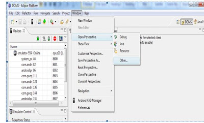
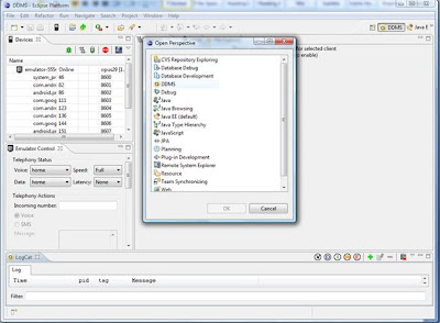
- To push songs on the emulator using Eclipse->Window->Open Perspective->Other->DDMS
- Choosing DDMS.
- the DDMS dialog box opens up ... on right side, we have tabs like @File Explorer ... there is sdcard folder with d--rxrwx permissions.

- Drag and Drop the audio / music files and picture files to this card with all the extensions like .wma, mp3, etc.

- This is how it looks finally in SDcard.

- Play files on the emulator. However if you have problems running any files on emulator, try to re-run the instance of the emulator after closing using the same command C:\android-sdk-windows-1.5_r3\tools>emulator -sdcard mysdcard.img -avd opus29.

- This is how the picture folder will look like.

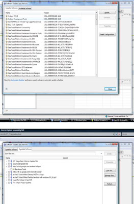
- Follow the following steps have to be redone if you have changed the version of android SDK and not updated eclipse. http://developer.android.com/sdk/1.5_r3/upgrading.html
Subscribe to:
Posts (Atom)