Thursday, July 30, 2009

How to Create SD Card?


The following commands will create, mount the SD card and finally push the songs to the SD card and emulator playing those songs/pictures.
  1. C:\android-sdk-windows-1.5_r3\tools>mksdcard -l sd500m 500M C:\android-sdk-windows-1.5_r3\tools\mysdcard.img ...... mksdcard: create a blank FAT32 image to be used with the Android emulator
    usage: mksdcard [-l label]

    if is a simple integer, it specifies a size in bytes
    if is an integer followed by 'K', it specifies a size in KiB
    if is an integer followed by 'M', it specifies a size in MiBto create sdcard

  2. The following size file will be created in tools directory of android-SDK. You can also create SD card with any memory size - say, 256M, 512M, 1024M, 2048M.

  3. To mount on emulator without specifying -avd C:\android-sdk-windows-1.5_r3\tools>emulator -sdcard mysdcard.img
    emulator: ERROR: You did not provide the name of an Android Virtual Device
    with the '-avd ' option. Read -help-avd for more information.

    If you *really* want to *NOT* run an AVD, consider using '-data 'to specify a data partition image file (I hope you know what you're doing). However, this command will work fine with android-sdk-windows-1.0_r1 (as in my previous post).
  4. The correct command to mount SD card is on latest android version is ..... C:\android-sdk-windows-1.5_r3\tools>emulator -sdcard mysdcard.img -avd opus29

  5. However, if, the emulator instance is already running, it gives the following error: emulator: ERROR: the user data image is used by another emulator. Aborting (so close the running emulator and then type again the following command).
  6. C:\android-sdk-windows-1.5_r3\tools>emulator -sdcard mysdcard.img -avd opus29 (this will run the new emulator instance with the SD card on it).
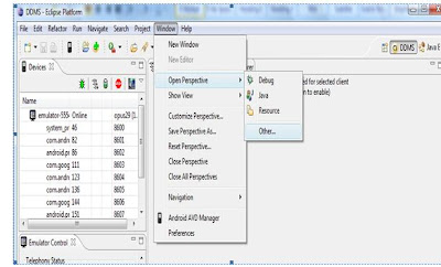
  7. To push songs on the emulator using Eclipse->Window->Open Perspective->Other->DDMS

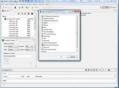
  8. Choosing DDMS.

  9. the DDMS dialog box opens up ... on right side, we have tabs like @File Explorer ... there is sdcard folder with d--rxrwx permissions.
  10. Drag and Drop the audio / music files and picture files to this card with all the extensions like .wma, mp3, etc.

  11. This is how it looks finally in SDcard.

  12. Play files on the emulator. However if you have problems running any files on emulator, try to re-run the instance of the emulator after closing using the same command C:\android-sdk-windows-1.5_r3\tools>emulator -sdcard mysdcard.img -avd opus29.

  13. This is how the picture folder will look like.


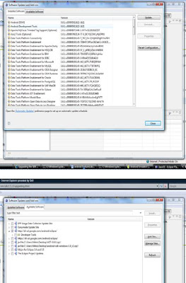
  14. Follow the following steps have to be redone if you have changed the version of android SDK and not updated eclipse. http://developer.android.com/sdk/1.5_r3/upgrading.html
Wednesday, July 29, 2009

Embedded System Project

Distance Sensor & Motion Sensor to Fade/Turn ON LED:

Objective: To sense the object closer or farther from the Distance Sensor which in turn controls the intensity of the LED or if motion is detected should turn ON the LED.

Circuit Diagram:


Flowchart for Distance Sensor:

Flowchart for Motion Sensor:

Material Used:

1. FreeScale Motorola M52233demo board.

http://www.freescale.com/webapp/sps/site/prod_summary.jsp?code=M52233DEMO&fsrch=1

2. Sensors from Parallax.

Ping))) Ultrasonic Sensor(for object detection) and PIR sensor (for motion detection)

http://www.parallax.com/tabid/176/List/0/CategoryID/51/Level/a/Default.aspx?SortField=ProductName,ProductName

3. Breadboard

http://www.radioshack.com/search/index.jsp?kwCatId=&kw=breadboard&origkw=breadboard&sr=1

4. Tools and Equipments

5. LED

http://www.globalsources.com/manufacturers/Square-LED.html

6. CodeWarrior Software

Related links:

  1. Ping Ultrasonic Range Finder, http://arduino.cc/en/Tutorial/Ping?from=Tutorial.UltrasoundSensor
  2. Blink, http://www.arduino.cc/en/Tutorial/Blink
  3. http://www.arduino.cc/playground/Main/UltrasonicSensor
  4. The World Famous Index of Arduino & Freeduino Knowledge http://www.freeduino.org/

1. Circuit Breaker
2. Current Transformer
3. Voltage Transformer
4. Transformer
5. Auto Winding Transformer
6. Lightning Arrestor
7. Surge Arrestor
8. Series Reactor
9. Shunt Reactor
10.

Features on Android /Google Phone

  1. Run cmd prompt.
  2. To change the path to tools directory of the current Android-SDK.
    C:\Users\Mark>cd C:\android-sdk-windows-1.5_r3\tools
  3. If directly try to run emulator.exe as in case of version android-sdk-windows-1.0_r1, we get the error and emulator does not run in this current version.
  4. However even when we directly try to run the emulator using command line, we need to create the android virtual device; for e.g.
    C:\android-sdk-windows-1.5_r3\tools>emulator.exe
    emulator: ERROR: You did not provide the name of an Android Virtual Device
    with the '-avd ' option. Read -help-avd for more information.

    If you *really* want to *NOT* run an AVD, consider using '-data '
    to specify a data partition image file (I hope you know what you're doing).
  5. Therefore, this is how we create avd (android virtual device)
    create avd using command:
    android create avd –n -t

    for e.g.
    C:\android-sdk-windows-1.5_r3\tools>android create avd -n opus29 -t 1
    Android 1.1 is a basic Android platform.
    Do you wish to create a custom hardware profile [no] Enter
    Created AVD 'opus29' based on Android 1.1

  6. You can get target ID from:
    C:\android-sdk-windows-1.5_r3\tools>android list targets
    Available Android targets:

    id: 1
    Name: Android 1.1
    Type: Platform
    API level: 2
    Skins: HVGA (default), HVGA-L, HVGA-P, QVGA-L, QVGA-P
    id: 2
    Name: Android 1.5
    Type: Platform
    API level: 3 Skins: HVGA (default), HVGA-L, HVGA-P, QVGA-L, QVGA-P
    id: 3
    Name: Google APIs
    Type: Add-On
    Vendor: Google Inc.
    Description: Android + Google APIs
    Based on Android 1.5 (API level 3)
    Libraries:
    * com.google.android.maps (maps.jar)
    API for Google Maps
    Skins: QVGA-P, HVGA-L, HVGA (default), QVGA-L, HVGA-P
  7. To run emulator with the create avd:
    C:\android-sdk-windows-1.5_r3\tools>emulator -avd opus29

    Android Emulator initializing and opening screen display:
    Android Emulator (opus29: 5554)
    5554 is the port number of this emulator.
  8. Playing with the front screen and hitting the PULL-UP ARROW tab will have the following page on display and have the following default Applications:
    a. Alarm Clock
    b. Browser
    c. Calculator
    d. Camera
    e. Contacts
    f. Dev Tools
    g. Dialer
    h. Email
    i. Maps
    j. Messaging
    k. Music
    l. Pictures
    m. Settings.

  9. MENU tab: This will open up and it has options:
    a. WALLPAPER
    b. ADD
    c. SEARCH
    d. NOTIFICATIONS
    e. SETTINGS

  10. Lets see WALLPAPER. Here Select Wallpaper from Pictures or Wallpaper Gallery. I choose picture from the gallery and did Set Wallpaper.


  11. NOTIFICATIONS; will notify all the current activities.

  12. ADD: a. All 13 Applications listed above can be added b. Shortcuts - Folders, Bookmark, Contact, Music Playlist c. Widget - Clock, Picture Frame, Search d. Wall Paper.

  13. SEARCH: will open the google search engine.
  14. SETTINGS
  15. DIALER

Tuesday, July 28, 2009

Electrical Interview Questions such as SOTF, Stubbus, Breaker Fail

Switch On To Fault (SOTF):

  • Switch On To Fault Schemes are protection functions intended to trip a transmission line breaker when closed on to a faulted line.
  • If you are switching on to fault,Voltage is not going to rise as it should and fault current as decided by the fault MVA is going to flow.Many Line protections include this SOTF protection as a built inlogic.The closing of CB enables the logic for a set time say 200ms.If the Voltage does not rise to 50-60 % of the rated voltage in onecycle & if the current is more than the set current it is sensed as a SOTF and a three phase tripping impulse is given and recloser isblocked.
  • With the offset-zone time delay bypassed, there can be provision on SOTF protection. This is required where there are Line-side Voltage Transformers, to provide fast tripping in the event of accidental line energization with maintenance earthing clamps left in position. (from chap 11 of NPAG, pg 175)
  • To detect SOTF, configure CB Open/Close Switch to the IED as its Binary Input for the closing pulse.

Stubbus Breaker:

  • Sensing of the state of the line isolator through auxiliary contacts enables the current values transmitted to and received from remote relays to be set to zero when the isolator is open. Hence, stub-bus protection for the energized part of the bus is then possible, with any fault result in tripping of the relevant CB.

Breaker Failure Stages:

  • When the outgoing feeder say, Transformer or Line or any Bay trips its CB using master trip relay, the contacts of the relay also initiates Breaker fail of the bus.
  • BF stage 1 – retrip its own breaker
  • BF stage 2 – initiate Intertrip and all those breakers which feed to the fault, in order to isolate the system.

Reference:

  1. Switch On To Fault Schemes in the context of Line Relay Loadability by North American Electric Reliability Council, Draft 2006. http://www.nerc.com/docs/pc/Itm_3b_att%20C_SOTFWhitepaperDraft5-31-06.pdf